3.9 Axis-X&Y Joystick Module
3.9.1 Overview
Axis-X&Y Joystick is a high-precision input device for bidirectional control. Its X and Y axes are separated to control horizontal and vertical movements respectively. This module contains 10K resistance so that it ensures the stability and accuracy of signals.
3.9.2 Schematic Diagram
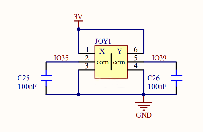
ESP32 Axis-X&Y Joystick works based on a two-axis potentiometer that detects movements on two axes. When the joystick moves on axis X or Y, the resistance of the potentiometer changes, outputting analog voltage signals. After being received by ESP32 analog input pin (ADC), these signals will be read by ESP32 board and converted to digital values. Therefore, the joystick coordinate can be easily revealed during controlling.
3.9.3 Code Blocks

This block reads the values of Axis-X&Y Joystick module. You can set pins and axis.
3.9.4 Test Code
3.9.4.1 Build Code
There are two ways to upload the code: directly open the code file we provide; or manually build blocks.
Directly open the code file we provide:
Click
 and choose
 Load from your computer
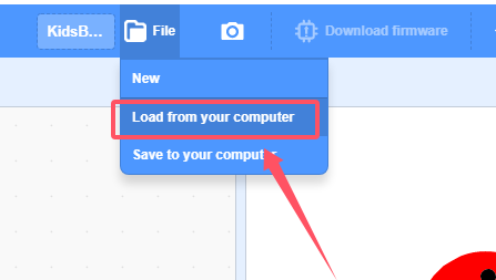
We have already downloaded the codes on computer desktop, so open the file and choose
3-9-joystick.sb3
Manually build blocks:
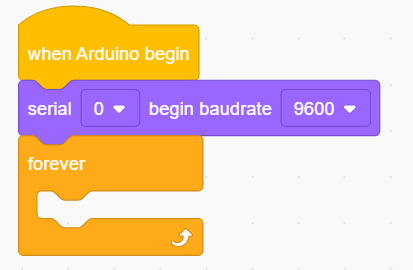
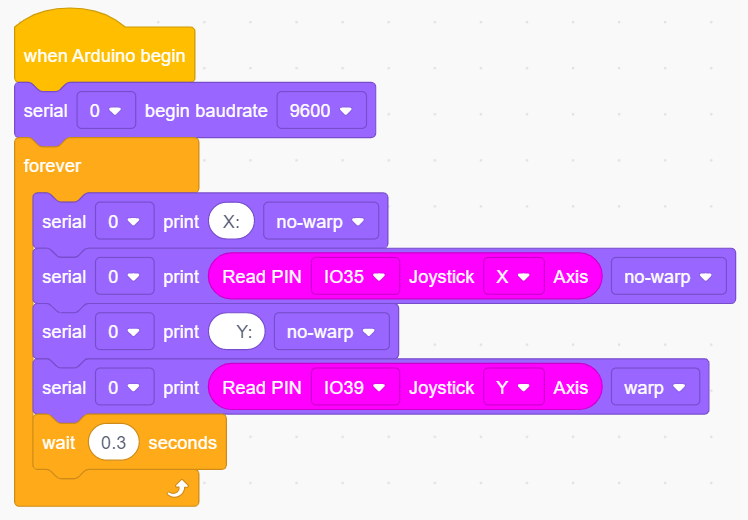
In
 , find
  block.
In
 , find
 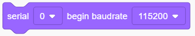 block and set baud rate to 9600, and put it under .
In
 , drag
  .
.
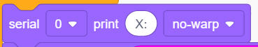
In
, put 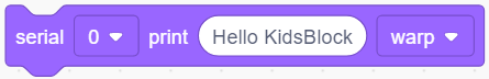 into , change printing content into “X:” and set to no-warp.
Add another
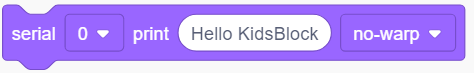 and set to no-warp
In
 , find and drag block into the printing content box of , set pin to IO35 and axis to X
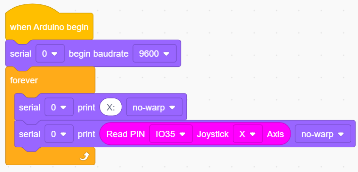
Duplicate block
 , and modify the printing content “X:” into “ Y:”(the two spaces separates the two values to be output). Change pin to IO39 and set axis to Y.
Add a delay of 0.3s for better observing results.
Complete Test Code
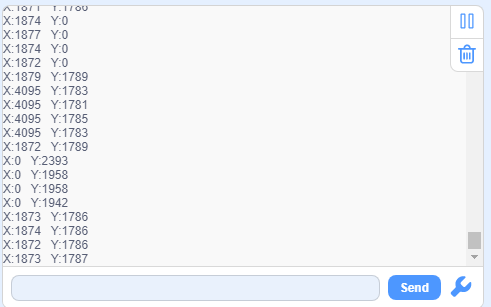
3.9.4.2 Test Result
After uploading code, the serial monitor prints the values on axis X and Y. Toggle the joystick, and these value changes.