3.12 (Direction Recognition) Geomagnetic Sensor
3.12.1 Overview
AK8975C geomagnetic sensor is a three-axis electronic compass IC with high sensitivity. It can output 13-bit data and accurately detect X, Y, Z axes geomagnetic values. Thus, it is suitable for portable devices with navigation function such as mobile phones and tablets.
3.12.2 Schematic Diagram
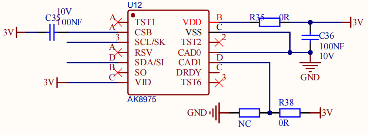
The AK8975C geomagnetic sensor works in the principle of electromagnetic induction. It takes the Earth’s magnetic field as a measurement benchmark to sense changes in the magnetic field through its internal magnetic material and coils. Specifically, when the magnetic material is affected by geomagnetic field, a directional constrained electron spin deflection will happen due to the field force, which in turn forms a magnetic field. This field induces potential signals in the coil.
This sensor amplifies and processes the induced potential signals, which are then transmitted to the system for further calculation, analysis and processing. So it measures geomagnetic magnetic field in the axis X, Y, and Z to determine the direction.
3.12.3 Code Blocks

This block is used to initialize AK8975 geomagnetic sensor.

This block reads the magnetic field direction.

This block reads the values on axis X, Y and Z:

3.12.4 Test Code
3.12.4.1 Build Code
There are two ways to upload the code: directly open the code file we provide; or manually build blocks.
Directly open the code file we provide:
Click
 and choose
 Load from your computer
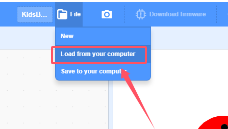
We have already downloaded the codes on computer desktop, so open the file and choose
3-12-ak8975.sb3
Manually build blocks:
In
 , find
  block.
In
 , put under
 In
 , drag
  and set baud rate to 9600, and put it under
 In
 , drag
  .
.

In
, put  in and set to print “X:” in no-warp mode.
Add a
 and set to no-warp mode.
In
, put into the printing content of , and set to read axis “X”.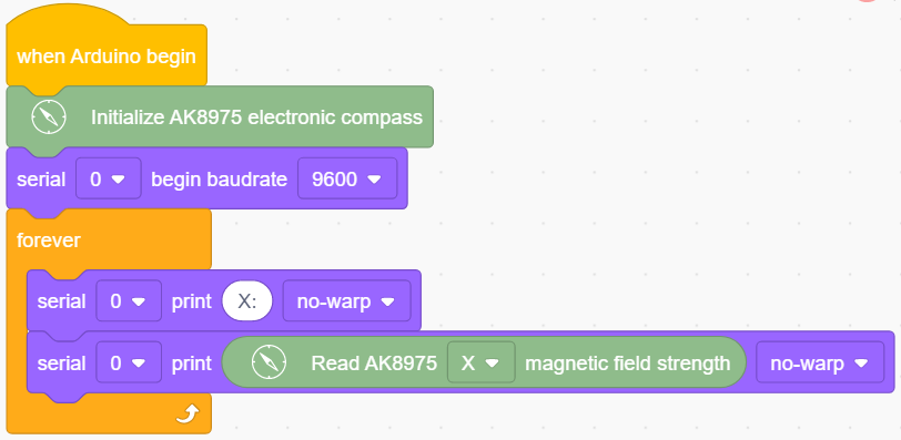
Duplicate
 and change to read “ Y:”(the two spaces separates the two values to be output). Set to read value in axis “Y”.
Duplicate
 and change to read “ Z:”(the spaces separates the two values to be output). Set to read value in axis “Z”.
Duplicate
 and change to read “ Direction:”(the spaces separates the two values to be output).
In
, put into the printing content of and set mode to warp.Add a delay of 1S for better observing the results.
Complete Test Code

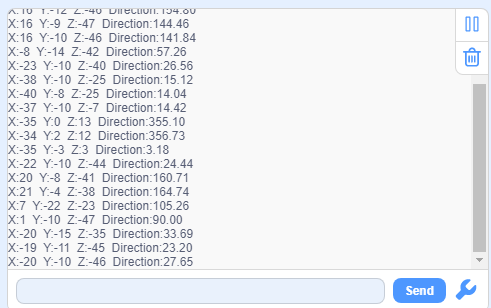
3.12.4.2 Test Result
After uploading code, the serial monitor prints the sensor values. Move the coding box to see the changes of these values.