3.1 LED Blink
3.1.1 Overview
LED Blink is one of the simplest entry-level programming projects. It only needs an LED and then upload the code This simple project helps beginners better master basic concepts.
3.1.2 Schematic Diagram
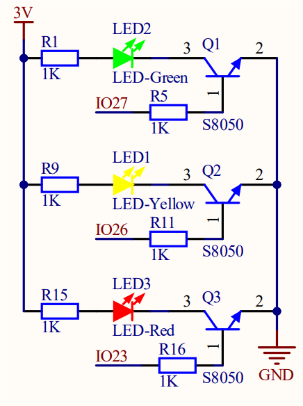
LED lighting on: The output current of the IO ports is limited, so the LED brightness may not be enough. Therefore, a NPN triode (Q2) is added to the circuit as a switch. We only need to add a high(low) level at the triode base pin 1 to light it up(out).
Triode on/off: To put it simple, when the base(pin 1) receives a high level, the collector(pin 3) and the transmitter(pin 2) are connected, so then VCC passes through the current-limiting resistor to the LED and then into the triode to GND, forming a loop. At this time, LED is on. When pin 1 receives a low level, pin 3 and 2 are disconnected so the current loop cannot be formed, resulting LED off.
3.1.3 Code Blocks

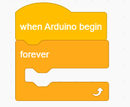
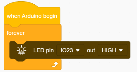
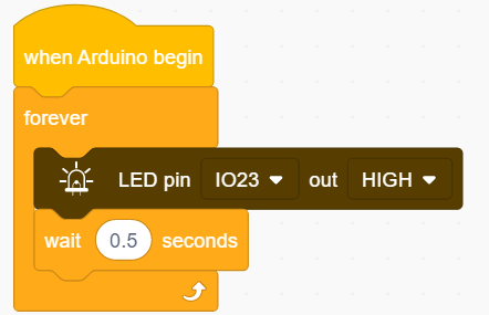
The start of the execution of a code. Codes will not run without this block. The module blocks that need to be initialized should be added below the block.

Code run in here and are executing all the time (in a loop).

This block controls the ON/OFF of an LED. You only need to set the pin and power level(HIGH/LOW).

The delay seconds can be modified as needed.
Unit: s.
Some conversions: 1S=1000mS; 1mS=1000uS; For instance, if a delay of 10ms is required, input 0.01.
3.1.4 Test Code
3.1.4.1 Build Code
There are two ways to upload the code: directly open the code file we provide; or manually build blocks.
Directly open the code file we provide:
Click
 and choose
 Load from your computer
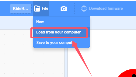
We have already downloaded the codes on computer desktop, so open the file and choose
3-1-led.sb3
Manually build blocks:
In
 , find block.
In
 , find and place block under .
In
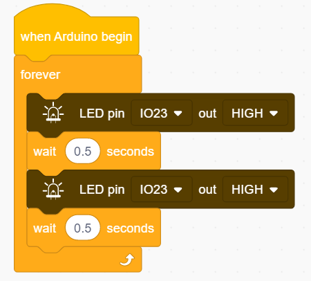
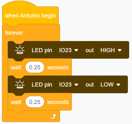
 , drag and put block into . Set pin to IO23 and output to HIGH.
In
, add a delay of 500ms. So we set it to 0.5s.
Right-click
and you will see  . Choose
 Duplicateand put the copy under :
:
Modify
output into LOW.

3.1.4.2 Test Result
After uploading code, the red LED will blink with an interval of 0.5 seconds.
3.1.5 Extension
If you want the LED to blink more frequently, just modify the delay time in . If we set the time shorter, it will blink faster. Now let’s set it to 0.25s.
3.1.5.1 Test Code
There are two ways to upload the code: directly open the code file we provide; or manually build blocks.
Directly open the code file we provide:
Click
and choose Load from your computer
We have already downloaded the codes on computer desktop, so open the file and choose
3-1-led2.sb3
Manually build blocks:
Build code blocks as above but set delay to 0.25.
3.1.5.2 Test Result
After uploading code, the red LED will blink with an interval of 0.25 seconds. Compared to 3.1.4.1, it blinks more frequently.