3.8 RFID Sensor
3.8.1 Overview
RFID-RC522 module adopts Phillips MFRC522 original chip in card reading circuit, which is easy to use and with low cost. It is suitable for equipment and reader development, advanced applications, RF card terminal design and producing.
3.8.2 Schematic Diagram
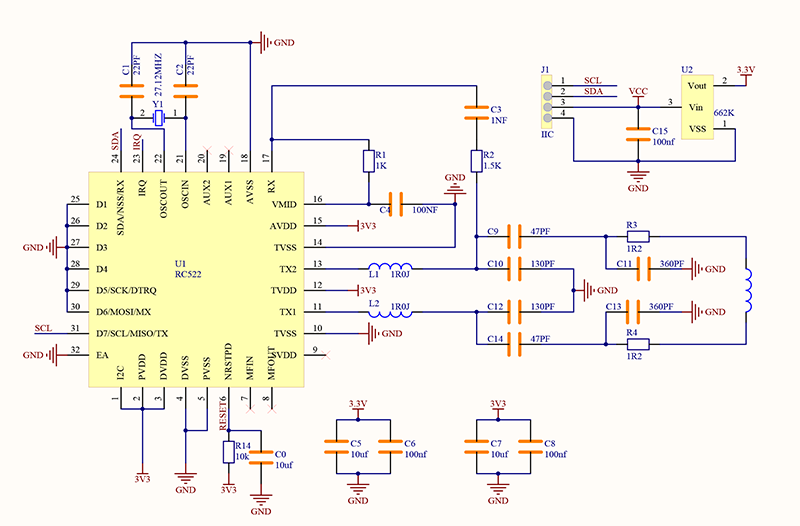
RFID (Radio Frequency Identification):
The card reader is composed of a frequency transmitter module and a high level magnetic field. The Tag transponder is a device to be sensed without a battery. It consists only of tiny integrated circuit chips, media for storing data, and antennas for receiving and transmitting signals. To read the data in the tag, it must be placed within the reading range of the reader. After that, the reader will generate a magnetic field. According to Lenz’s law (magnetic energy generates electricity), the RFID Tag will be powered, thus activating the device.
NOTE: this module only recognize card working at 13.56MHz. It is recommended to use the provided card in the kit.
3.8.3 Code Blocks

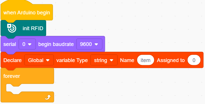
This block initializes RFID module. Without it, its data cannot be read.

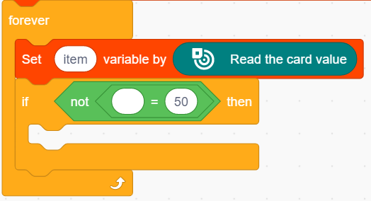
This block reads the card value of the RFID sensor.

This is a comparison block that determines whether the value of two parts equals each other. When they are equal, it outputs 1, or else it outputs 0.

This is a logical block to reverse the value. That means this block outputs 0 when the condition block outputs 1, and it outputs 1 when the condition outputs 0. It reverses outputs.

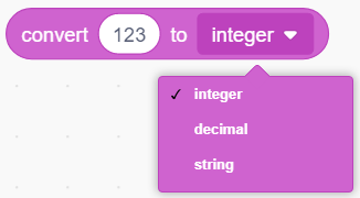
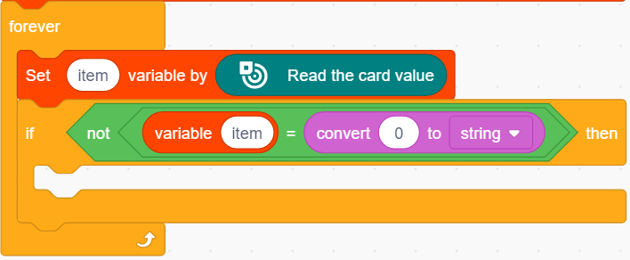
This is a conversion block that converts values into one of types of integer, decimal or string.
3.8.4 Test Code
3.8.4.1 Build Code
There are two ways to upload the code: directly open the code file we provide; or manually build blocks.
Directly open the code file we provide:
Click
 and choose
 Load from your computer
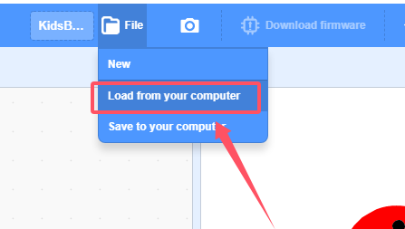
We have already downloaded the codes on computer desktop, so open the file and choose
3-8-rfid.sb3
Manually build blocks:
In
 , find
  block.
In
 , find and put under
 In
 , find
  and set baud rate to 9600
In
 , put
, put  under
under  , and set variable Type to
 stringIn
 , put
, put  below the block
In
, place  in
in In
 , put in the right box of block
 In
, add a 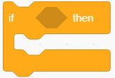 under
under 
In
 , put into the condition box of
 In
, put into the condition box of
In
, put  into the left part of
 In
 , put into the right part of and modify the conversion value to “0” and conversion type to “string”.
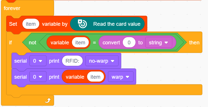
In
, find  and put it into
 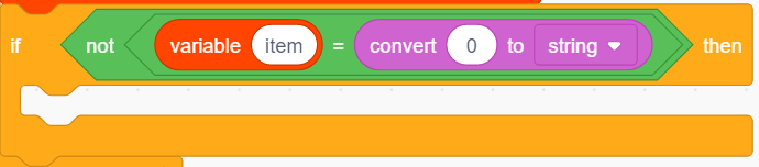 , and modify the printing content into “RFID:” and set printing mode to no-warp.
Drag another
, and then add a variable block into the printing content box.
As follows:
Complete Test Code
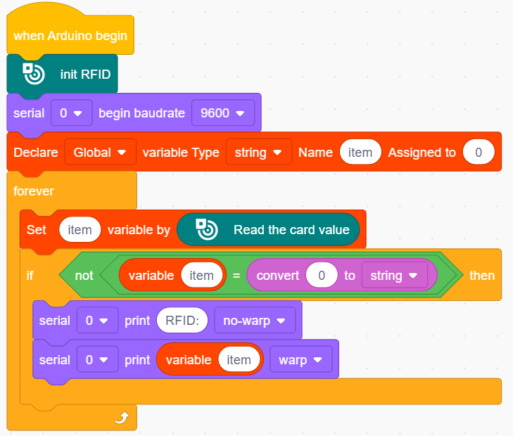
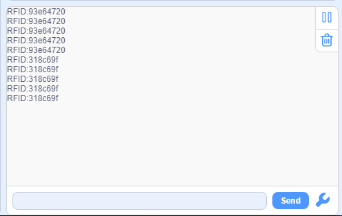
3.8.4.2 Test Result
After uploading code, cover the RFID sensing area with the IC card or the key in the kit, and you will see the serial monitor prints the ID numbers.