3.6 AD Button
3.6.1 Overview
The AD button requires only one analog pin to read multiple button states, which greatly saves IO ports. It adopts analog acquisition, and the output voltages vary from pressed buttons, so that different analog values can be obtained. We can determine which button is pressed according to these values.
3.6.2 Schematic Diagram
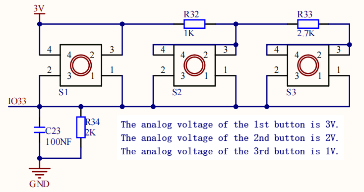
From the Schematic Diagram:
When no button is pressed, the output at signal pin IO33 is pulled down by R34 (connected to GND. So the analog value of IO33 is 0, that is, low level 0V;
When button S1(the red button) is pressed, pin IO33 is connected to VCC. So the analog value of IO33 is 4095 (voltage = 3.3V).
When button S2(the yellow button) is pressed, the voltage of IO33 is that between R32 and R34: VCCxR34/(R32+R34) ≈ 2.2V, and the analog value is about 2432;
When button S3(the green button) is pressed, the voltage of IO33 is that between R32+R33 and R34: VCCxR34/(R32+R33+R34) ≈ 1.1V, and the analog value is about 1175.
3.6.3 Code Blocks

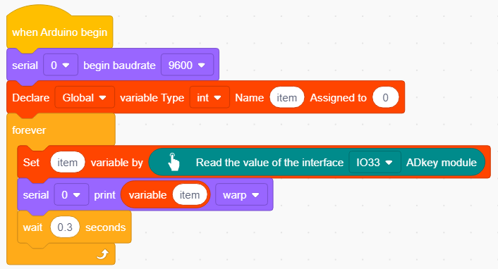
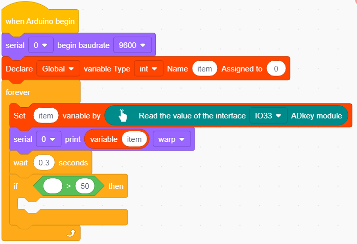
This block reads the analog value of AD button module and determines which button is pressed according to this value.

This block declares variables. Its type is int by default. You can input a Name and an Assignment(initial value).

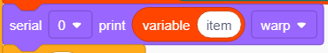
This block records a value of a variable so that we can directly use it to replace the value. Before using, you only need to modify its name into the needed variable.

This block assigns a value to a variable. For example, we need to assign 100 to variable val, just input the variable name and value in the block accordingly.

This is a comparison block that compares the values on both sides. If the left one is greater than the right one, output 1; or else, output 0.

Similarly, this is also a comparison block. If the left one is lower than the right one, output 1; or else, output 0.

This is a logical block with two condition boxes. Only when both sides output 1, this block outputs 1. One or both of the two sides output 0, and this block will output 0.
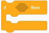
This “if…then” block determines conditions. Put condition(s) in the diamond box to output 1 or 0 (as above introduced). If 1 is output, execute the following codes; If it is 0, do not execute.
3.6.4 Test Code
3.6.4.1 Build Code
There are two ways to upload the code: directly open the code file we provide; or manually build blocks.
Directly open the code file we provide:
Click
 and choose
 Load from your computer
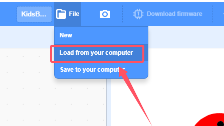
We have already downloaded the codes on computer desktop, so open the file and choose
3-6-adKey.sb3
Manually build blocks:
In
 , find
  block.
In
 , find
 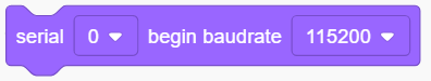 block and set baud rate to 9600, and put it under .
In
 , find and drag block under
  .
.In
 , put
, put 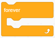 under
under In
, put into In
 , find and put it into the variable name box in
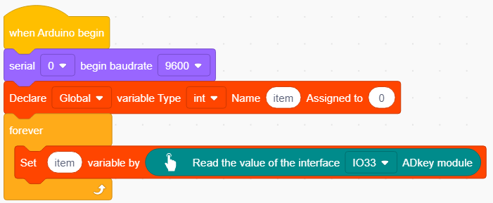
In
, place 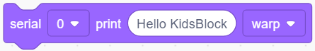 under
under
In
, put intoAt last, add a delay of 0.3S for better observing results.
Complete Test Code
3.6.4.3 Test Result
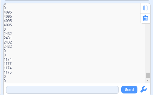
After uploading code, the serial monitor will print the analog value of the module. When the red button is pressed, the value is about 4095, and the yellow is about 2432, and the green is about 1175. If no button is pressed, the value equals 0.
3.6.5 Extension
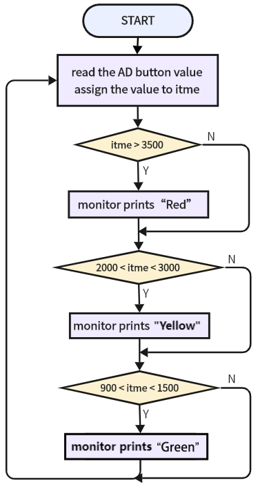
3.6.5.1 Code Flow
AD button logic table:
Button |
the analog value of button being pressed |
the analog value of button being released |
|---|---|---|
the red button |
4095 |
0 |
the yellow button |
about 2432 |
0 |
the green button |
about 1175 |
0 |
3.6.5.2 Test Code
There are two ways to upload the code: directly open the code file we provide; or manually build blocks.
Directly open the code file we provide:
Click
and choose Load from your computer
We have already downloaded the codes on computer desktop, so open the file and choose
3-6-adKey2.sb3
Manually build blocks:
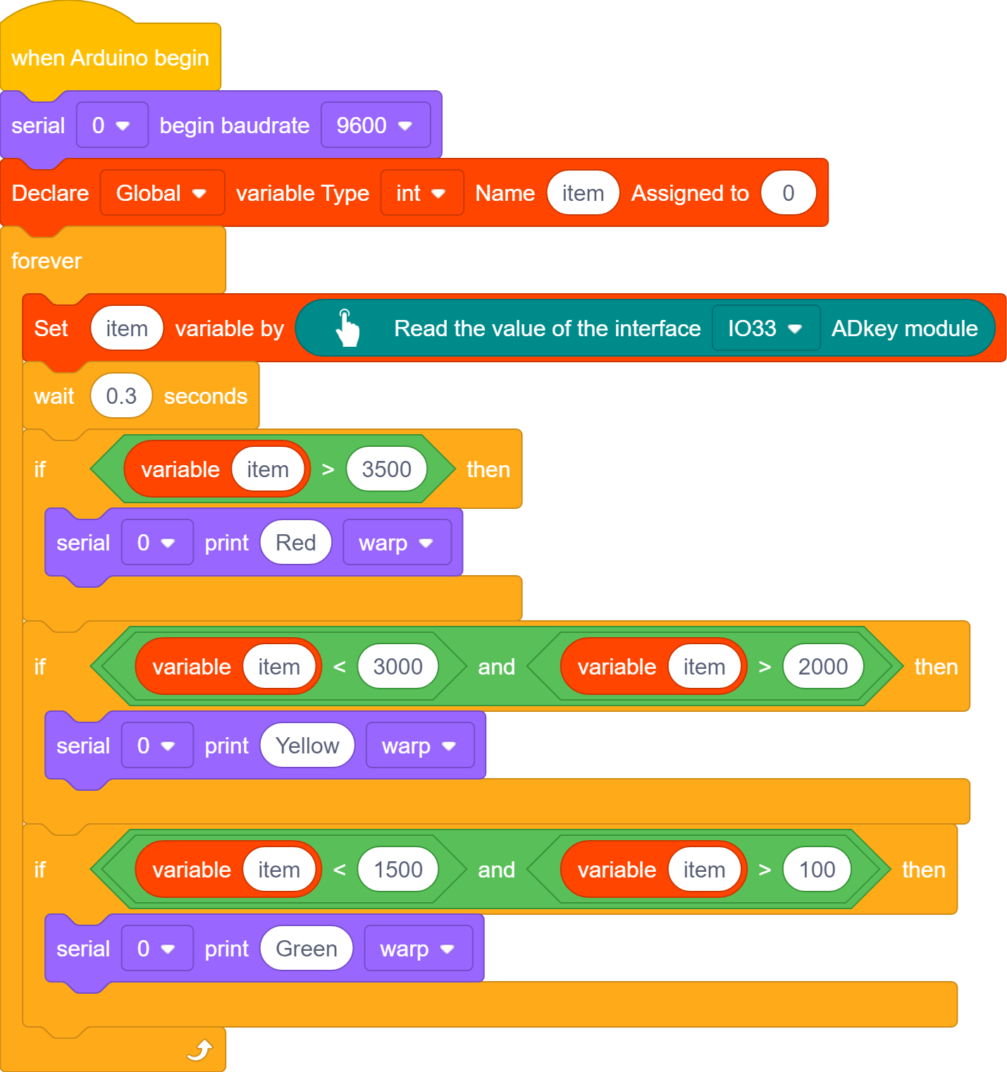
Based on 3-6-adKey.sb3, we add a condition statement to determine the read analog value of AD button module so that we can tell which button is pressed.
Remove block
 : just click Delete
In
, put under 
In
 , put into the condition box of
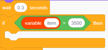
In
, put into the left part of , and input 3500 in the right: itme > 3500
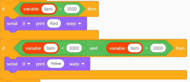
In
, put into the “if…then” block and modify the printing content into “Red”, so as to determine whether the red button is pressed.

In
, drag under In
, put into the condition box of In
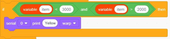
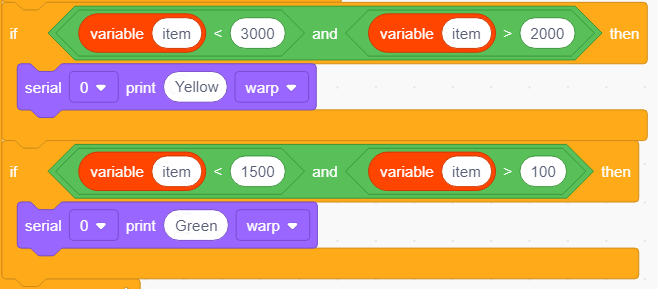
, find block , and put in its left part and modify the right part to 3000: item < 3000In
, find block , and put in its left part and modify the right part to 3000: item > 2000Put
 into respectively.
Add a
under , and modify the printing content into “Yellow”.
Duplicate
 and modify 3000 to 1500, and 2000 to 100, and printing content into “Green”:
Complete Test Code
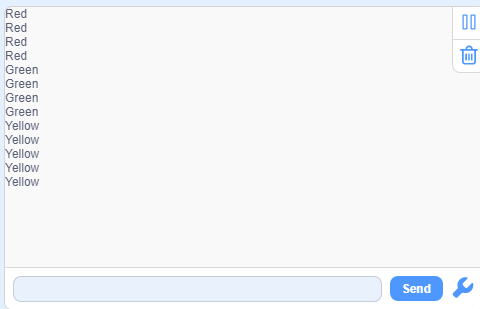
3.6.5.3 Test Result
After uploading code, the serial monitor will print the colors of the buttons. If one of the buttons is pressed, its color will be displayed: “Red”, “Green” or “Yellow”.