3.18 Breathing LED
3.18.1 Overview
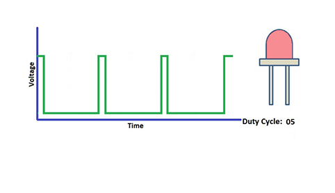
PWM breathing LED utilizes on-board programmable PWM to output analog waveform. After powering on, LED brightness can be adjusted through duty cycle of the waveform to eventually realize a breathing light.
In this way, ambient light can be simulated by changing LED brightness along with time. Also, breathing LED can form a colorful mini light show to construct a tranquil and warm environment.
3.18.2 Working Principle
PWM controls analog output via digital means, which are able to adjust the duty cycle of the wave (a signal circularly shifting between high level and low level).
digital ports of voltage output are LOW and HIGH, which respectively correspond to 0V and 5V. Generally, we define LOW as 0 and HIGH as 1. will output 500 signals of 0 or 1 within 1s. If they are 500 “1”s, 5V will be output. Oppositely, if they are all 0s, the output will be 0V. Or if they are 010101010101…, the average output will be 2.5V. In other words, output ratio of 0 and 1 affects the voltage value.
Honestly, it differs from real continuous output, yet the more 0 and 1 signals are output per unit time, the more accurate the control will be.
3.18.2 Code Blocks

This block will increase or decrease one on the value of the variable when it is execute each time. The variable name can be set. There are ++ and – – can be chosen: ++ add 1; – – minus 1.

This block the brightness of the LED. You need to set LED pin, channel and analog value of brightness(ranging from 0-255).
3.18.3 Test Code
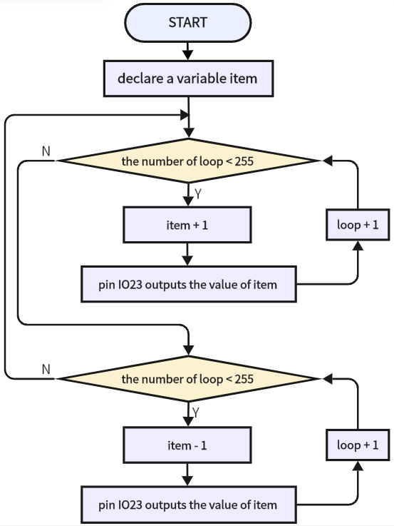
3.18.3.1 Code Flow
3.18.3.2 Build Code
There are two ways to upload the code: directly open the code file we provide; or manually build blocks.
Directly open the code file we provide:
Click
 and choose
 Load from your computer
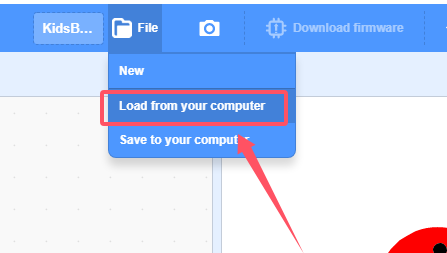
We have already downloaded the codes on computer desktop, so open the file and choose
3-18-gradientLight.sb3
Manually build blocks:
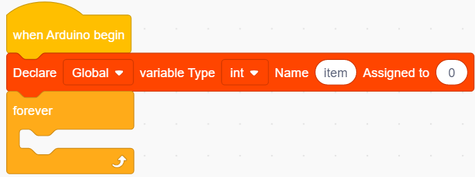
In
 , find
  block.
In
 , find and place
  block under .

In
 , drag block
  (keep the default) and put it under
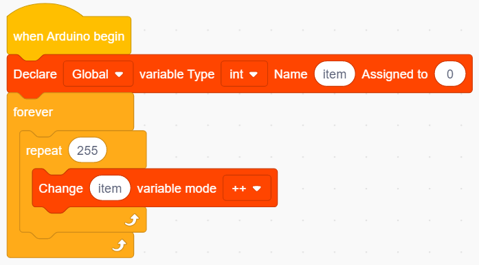
In
, drag  and set times to 255, put it in
 In
, put in 
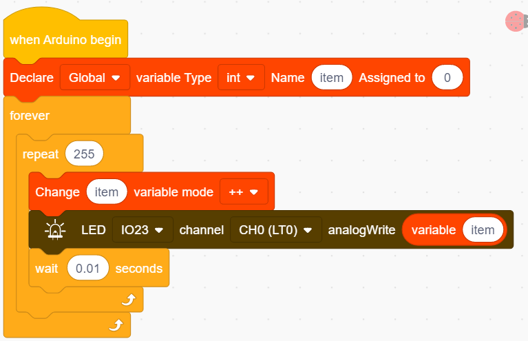
In
 , put under
 In
, find  and do not need to modify the name, put it in the analog value of .
Add a delay of 0.01S.
Duplicate
, modify ++ in into – –.
Complete Test Code

3.18.3.3 Test Result
After uploading code, the red LED gradually lights on and dims out, in a circulation. It “breathes” evenly.