3.1 LED Blink
3.1.1 Overview
LED Blink is one of the simplest entry-level programming projects. It only needs an LED and then upload the code on the ESP32 Coding Box. This simple project helps beginners better master basic concepts.
3.1.2 Schematic Diagram
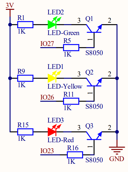
LED lighting on: The output current of the IO ports is limited, so the LED brightness may not be enough. Therefore, a NPN triode (Q2) is added to the circuit as a switch. We only need to add a high(low) level at the triode base pin 1 to light it up(out).
Triode on/off: To put it simple, when the base(pin 1) receives a high level, the collector(pin 3) and the transmitter(pin 2) are connected, so then VCC passes through the current-limiting resistor to the LED and then into the triode to GND, forming a loop. At this time, LED is on. When pin 1 receives a low level, pin 3 and 2 are disconnected so the current loop cannot be formed, resulting LED off.
3.1.3 Test Code
Code:
Open Thonny. Connect the board to computer and choose the port. In Files, open 3-1-led.py and click  .
.
'''
 * Filename    : 3-1-led
 * Thonny      : Thonny 4.1.4
 * Auther      : http//www.keyestudio.com
'''
from machine import Pin
import time

led = Pin(23,Pin.OUT) 	# Set IO23 as the red LED control pin,set pin to output

while True:
    led.on()			#red led on
    time.sleep(1)		#delay 1S
    led.off()			#red led off
    time.sleep(1)		#delay 1S
Result:
After uploading the code, red LED will blink with an interval of 1 second.
3.1.4 Extension
If you want the LED to blink more frequently, just modify the delay time to 200mS. Let’s have a try!
Code:
Open Thonny. Connect the board to computer and choose the port. In Files, open 3-1-led2.py and click .
'''
 * Filename    : 3-1-led2
 * Thonny      : Thonny 4.1.4
 * Auther      : http//www.keyestudio.com
'''
from machine import Pin
import time

led = Pin(23,Pin.OUT) 	# connect the led to pin IO23, set it to output

while True:
    led.on()				#red led on
    time.sleep_ms(200)		#delay 200mS
    led.off()				#red led off
    time.sleep_ms(200)		#delay 200mS
Result:
After uploading the code, the red LED will blink with an interval of 200mS. Compared to the previous experiment, it blinks more frequently.
3.1.5 Code Explanation
from machine import PinImport Pin from machine to enable its functions.
machine.Pin
machine.Pin(id,mode,pull,value)
id :ESP32 GPIO pin number. For example, if you enable GPIO23, fill in with 23.
mode :pin mode can be one of the followings:
Pin.IN(0) - set pin to input
Pin.OUT(1) - set pin to (normal)output
Pin.OPEN_DRAIN(2) - set pin to open drain output
pull :specifies whether the pin is connected to a (weak-)pull resistor; it is valid only at input mode, and can be one of the followings:
None - no pull-up/down
Pin.PULL_UP(1) - enable pull-up resistor
Pin.PULL_DOWN(2) - enable pull-down resistor
value :only work at Pin.OUT and Pin.OPEN_DRAIN mode; assign the initial output pin value. Or else, the peripheral state of the pin stays still. 0 is low(off) while 1 is high(on).
Pin.on() - set pin to high
Pin.off() - set pin to low
import timeImport time type so that its related functions can be adopted.
led = Pin23, Pin.OUT)connect LED to pin io23, set pin to output.
Q :Why “output”?
A :The code is written for the mainboard. For the board, pin io23 is outputting power levels (high or low) to the connected module.
while True:Statements in this function will execute in a loop.
Formula of while loop function:
while (condition):
    (statements)...
led.on()andled.off()At pin io23 on the mainboard, respectively output high(1) and low(0); i.e., output high(1)/low(0) to LED module to make it on/off.
time.sleep(1)Delay 1s.
time.sleep_ms(1)Delay 1ms, this is more common.
time.sleep_us(1)Delay 1us, this is a underlying code which is not commonly used.
Conversion: 1s = 1000ms, 1ms = 1000us
Q :Why delay?
A :If you output a high level to LED, it will be always on. Yet, we add a delay of 1s, so it lights up for only 1s. Delay time is the ON/OFF time of LED.